Product Structure Design Specifications - Mold Steel Selection and Cooling System
(1) Mold Steel Selection
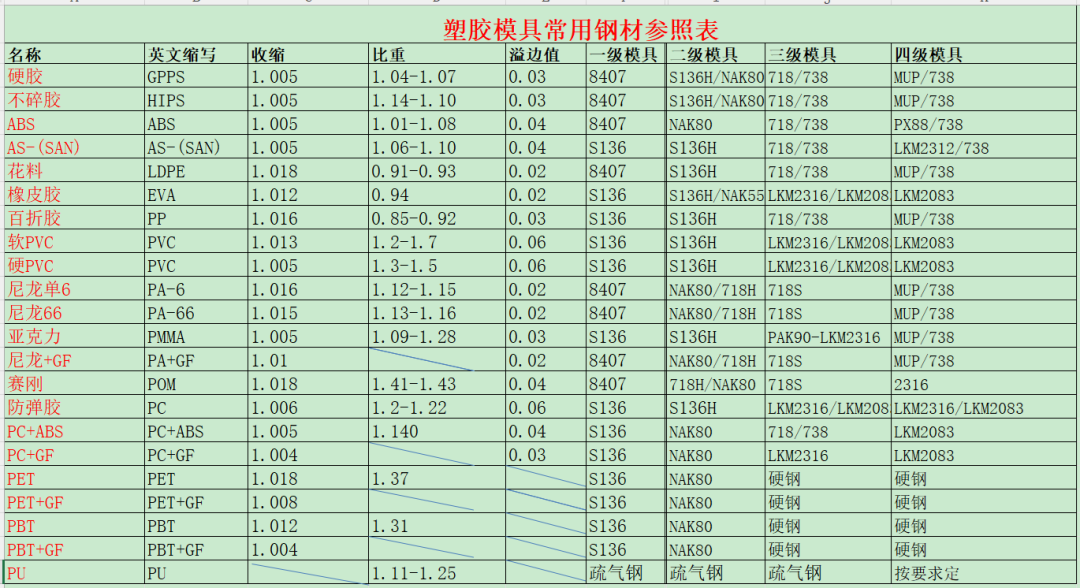
The choice of mold steel is determined by the characteristics of the molded part, surface treatment requirements, and the expected lifespan of the mold.
Factors Influencing Steel Selection:
-
Part Material Characteristics:
- Flame resistance
- Corrosion resistance
-
Part Surface Treatment:
- Mirror finish
- Ordinary polishing
- Texturing
- Engraving text and patterns
-
Mold Lifespan:
- The anticipated number of cycles and wear conditions.
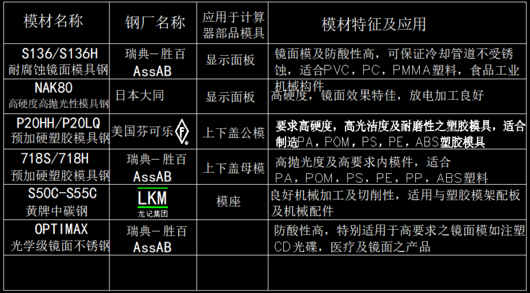
Common Plastic Mold Steels and Their Characteristics:
- P20: Good machinability, used for medium production runs.
- H13: High hardness, good thermal conductivity, suitable for high-temperature applications.
- S7: Tough, impact-resistant, used for high-stress molds.
- 4140: Good toughness and wear resistance, used for general-purpose molds.
(2) Mold Cooling System
Purpose of Cooling:
- Accelerate the solidification of molten plastic to shorten production cycles and improve efficiency.
- Enhance the quality of the molded parts.
Cooling Mediums:
- Typically water, oil, or in special cases, compressed air.
Cooling Principles:
- Ensure uniform temperature distribution across the mold.
- Maximize cooling efficiency.
Cooling Methods:
-
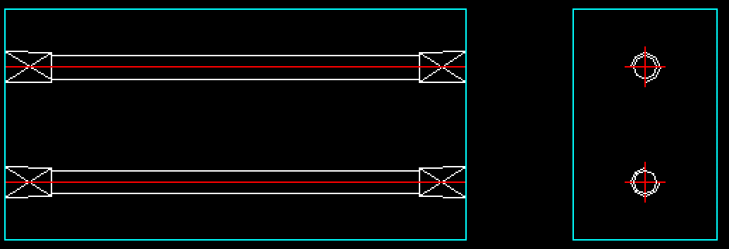
Direct Cooling:
- Water flows directly in and out of the mold, suitable for thin molds and flat products.
- Water flows directly in and out of the mold, suitable for thin molds and flat products.
-
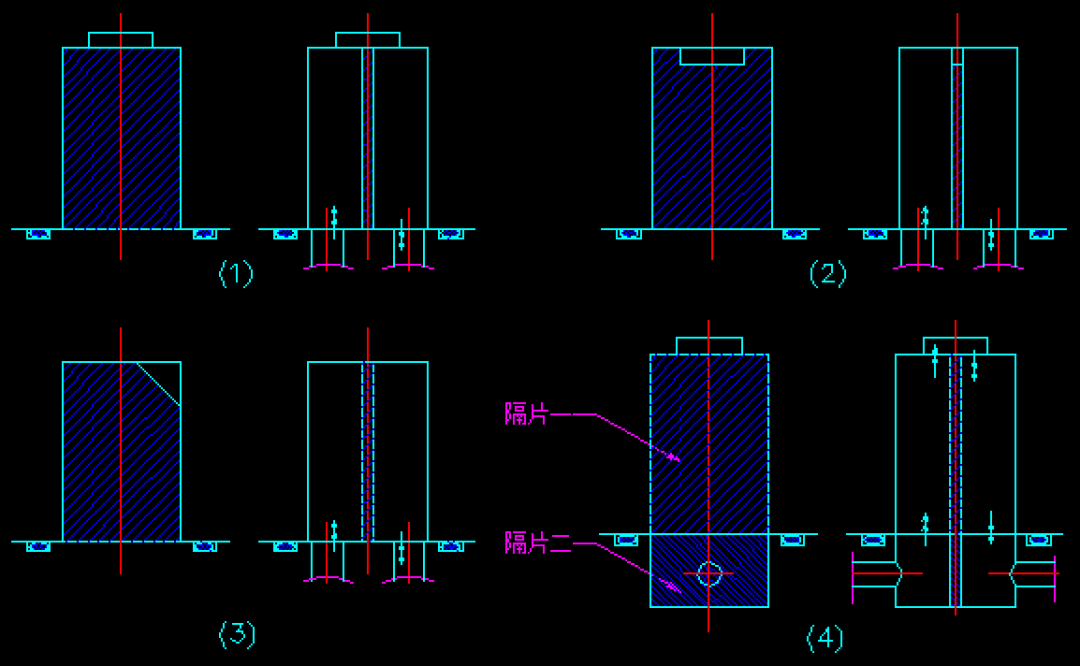
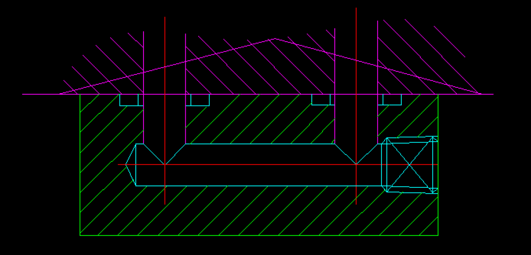
Spacer Cooling:
- Copper plates control the direction of the water flow, suitable for thicker molds, products with significant surface variations, and areas requiring focused cooling.
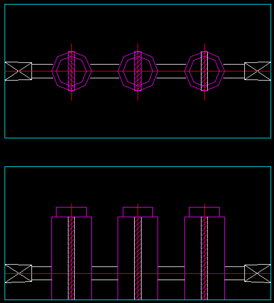
- Copper plates control the direction of the water flow, suitable for thicker molds, products with significant surface variations, and areas requiring focused cooling.
-
Thermal Conductive Cooling:
- Use high thermal conductivity materials like beryllium copper as inserts (in or out of contact areas), allowing direct contact of cooling water with most or all of the insert area.
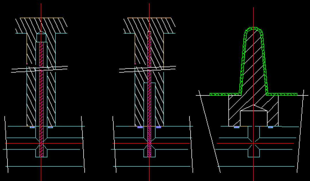
- Use high thermal conductivity materials like beryllium copper as inserts (in or out of contact areas), allowing direct contact of cooling water with most or all of the insert area.
-
Spray Cooling:
- Similar to spacer cooling but uses spray techniques.
-
Spiral Cooling:
- Cooling water creates a spiral flow within the mold, providing good cooling efficiency but is complex and costly to manufacture.
Cooling System Design:
- Ensure even shrinkage of the plastic part and maintain mold thermal balance.
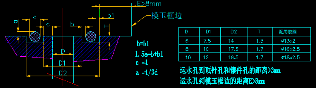
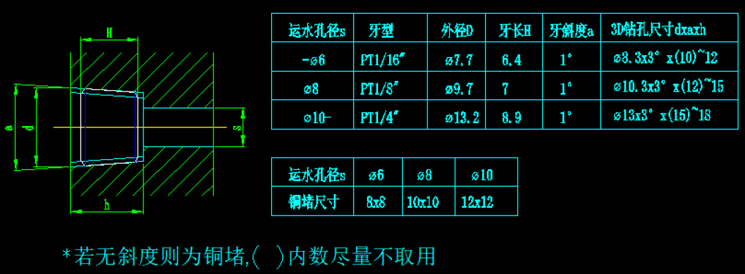
- Cooling water holes should be 6mm to 10mm in diameter, typically 8mm.
- Maintain the same distance between the cooling water holes and the mold surface, generally no less than 10mm. For uneven wall thickness, the distance at thicker sections should be slightly smaller.
- Strengthen cooling at the gate areas.
- Minimize the temperature difference between inlet and outlet water.
- Avoid placing cooling water channels close to weld lines on the plastic part.
- Maintain a distance of at least 4mm between ejector pins, cores, and cooling water channels.
- Ensure a minimum distance of 30mm between cooling water channel connections.
- Consider the structure of the part and characteristics of the plastic.
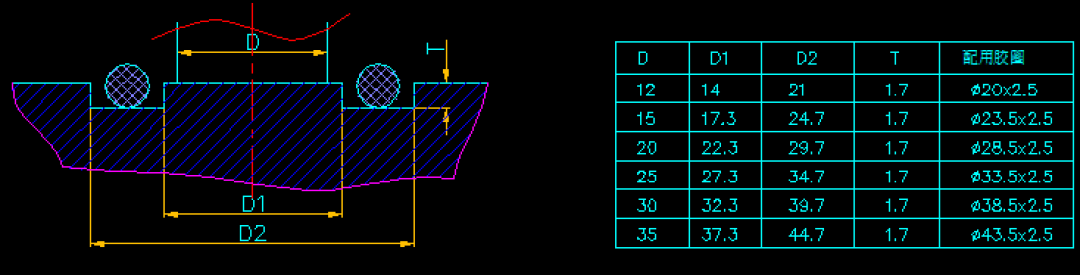
Cooling System Components:
- O-rings and Holes
- Water Jackets and Holes
- Adapters: For connection purposes.
- Water Plugs and Holes
- Spacers: Typically 2-4mm copper plates.