
(I) The relevant knowledge concerning the channel
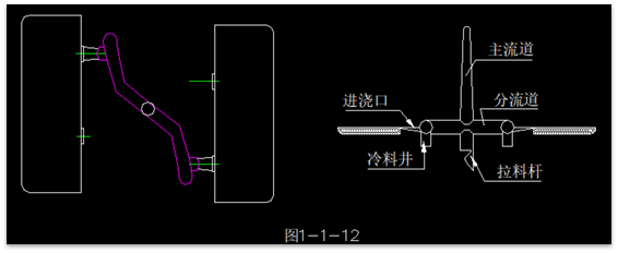
- The main channel refers to a section from the nozzle to the entrance of the runner, aligned on the same axis as the injection machine nozzle. The molten material in the main channel does not change direction.
- The runner is the section between the main channel and the gate(s). It is the passage through which the molten plastic enters the various cavities of a multi-cavity mold or multiple points of entry in a single-cavity mold, serving the functions of branching and redirecting. The runner is designed to minimize heat and pressure losses during plastic flow, while also minimizing the amount of plastic within the channel.
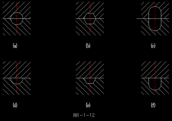
1. Cross-sectional Shape of Runners
If the cross-sectional area of the runner is too small, it will result in excessive pressure loss within the channel and reduce the amount of plastic delivered per unit of time, thereby prolonging the filling time. This may lead to defects such as uneven density, short shots, and surface waviness in the molded parts. On the other hand, if the cross-sectional area of the runner is too large, it not only increases the likelihood of air accumulation, leading to the formation of air bubbles in the parts, but also increases plastic consumption and extends the cooling time.
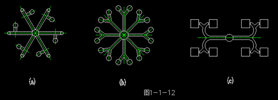
2. Distribution Forms of Runners
There are balanced and unbalanced distribution forms of runners, with the balanced form commonly used. In the balanced form, runners extend from the main runner to each cavity of the mold, with their lengths, shapes, and cross-sectional sizes all matching equally.
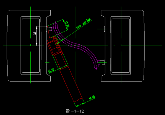
- The surface of the runners does not need to be very smooth; it should fix the cooling skin of the molten plastic, which is beneficial for insulation.
- When the runners are relatively long, a cold slug well should be provided at the end of the runner to accommodate the cold material at the beginning of injection, ensuring the quality of the molded parts.
- The junction between the runners and the sprue should be machined with a slope and transitioned with a rounded arc, which facilitates the flow and filling of plastic. Otherwise, it may create back pressure on the plastic and consume kinetic energy.
2. When designing the runners, consideration should be given to whether hot runner scissors can be used, as shown in the diagram.
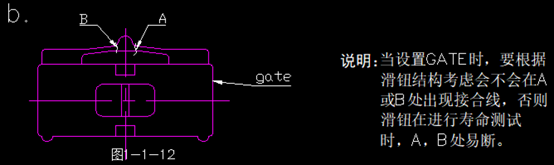
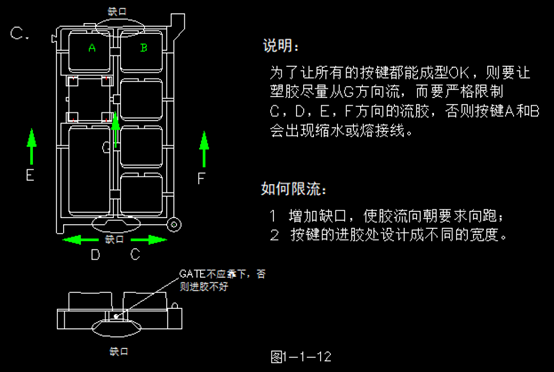
(II) Gate Location and Form for Injection
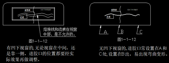
Improper positioning of the gate can lead to issues such as shrinkage, weld lines, air marks, and warping on the appearance of the part (as shown below). The gate is often placed on the hooks of the display panel, and it is important to remember to avoid openings in the cover.
The selection of gate locations on the display panel should consider avoiding weld lines and air marks. Even if unavoidable, these issues should not appear in visible or prominent areas such as the window zone.
Attachment:Common Classification and Applications of Injection Gate Types
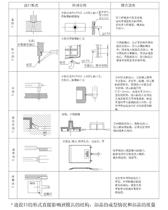
The form of the gate directly influences the mold's structure, the formation of parts, and their quality.